WhatsApp: +86 18126157548 Email: inquiry@alpinemold.com

Views: 0 Author: Site Editor Publish Time: 2026-08-03 Origin: Site


| 1. What Is Overmolding? |
| 2. Vital Design Considerations for Overmolding |
| 3. Common Materials Used for Overmolding |
| 4. The Advantages of Using Overmolding |
| 5. Conclusion |
Overmolding allows manufacturers to combine two materials into a single component, improving grip, durability, sealing performance, and product appearance. However, successful overmolding requires careful consideration of material compatibility, part design, and mold structure.
Overmolding is an injection molding process in which a second material is molded over a previously produced substrate. The substrate is normally a rigid plastic such as ABS, PC, PP, or Nylon, while the second material is often a softer TPE or TPU.
By combining materials with different properties, you can add soft-touch surfaces, improve grip, absorb impact, create sealing areas, reduce vibration, or protect sensitive components. Overmolding can also reduce the need for separate assembly, adhesives, screws, or additional seals.
Common applications include:
Tool handles and grips
Electronic housings and protective covers
Automotive interior components
Medical device handles
Buttons and control panels
Toothbrushes and consumer products
Cable strain relief and connector sealing
However, simply placing one material over another does not guarantee reliable bonding. Material compatibility, wall thickness, bonding structure, mold shut-offs, gate location, and processing conditions must all be considered during the design stage.
A successful overmolding project requires both a moldable product design and a mold structure that can accurately position the substrate, control the second-shot material, and prevent flash or deformation.
The design considerations can be divided into two areas:
Design guidelines for the overmolded part
Mold design considerations for overmolding
Wall Thickness
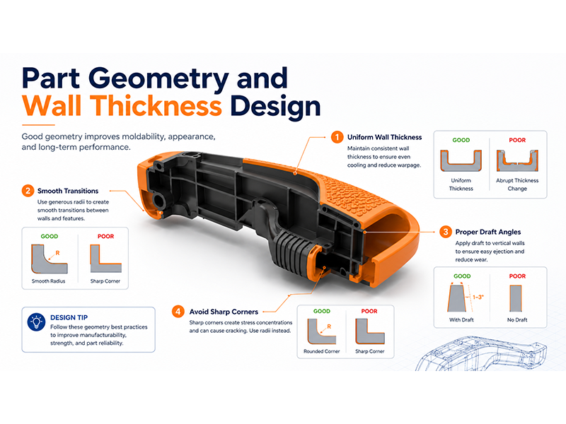
Uniform wall thickness is important for stable material flow, balanced cooling, and consistent shrinkage.
For many TPE and TPU overmolding applications, an overmold thickness of approximately 1.5–3.0 mm is a practical starting range. Very thin areas may freeze before the cavity is completely filled, while excessively thick areas may increase cooling time and create sink marks, internal stress, or deformation.You should avoid sudden changes between thick and thin sections. Smooth transitions and rounded corners help the overmold material flow more evenly and reduce stress concentration around the bonding interface.
Wall thickness should also be evaluated together with material hardness. A thin TPE layer may feel harder than expected, even when a relatively soft Shore A grade is used. Therefore, the final surface feel depends on both material hardness and overmold thickness.The actual thickness should always be confirmed according to the part size, flow length, material grade, bonding requirements, and product function.
Draft Angles
Soft overmold materials can stretch, drag, or tear during demolding, so sufficient draft is especially important.
A draft angle of approximately 2°–5° is commonly used on overmolded surfaces parallel to the ejection direction. Softer materials, deeper textures, and taller walls may require a larger draft angle.
Insufficient draft may cause:
Surface scratches
TPE tearing
Part sticking
Deformation during ejection
Increased mold wear
Longer production cycles
Textured surfaces require additional draft because the molded material must release from the texture depth. The final draft should therefore be selected according to the surface texture, material hardness, wall height, and ejection method.
Mechanical Interlocks
Chemical adhesion between the substrate and overmold material is important, but it should not always be the only bonding method.
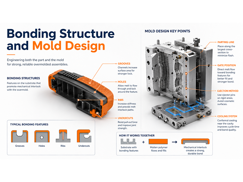
Mechanical interlocks allow the overmold material to physically lock onto or pass through the rigid substrate. They are particularly useful when the materials have limited chemical compatibility or when the product will experience repeated pulling, twisting, vibration, or peeling forces.
Common mechanical bonding features include:
Through-holes that allow the material to form a rivet-like lock
Grooves or channels that resist lateral movement
Undercuts and dovetail structures
Ribs and recessed areas
Wraparound edges
Openings that allow the overmold material to connect on both sides
These features should be designed according to the mold opening direction. Deep undercuts may require sliders, lifters, or other movable mold structures, which can increase mold complexity and cost.
A good overmolding design normally combines suitable chemical adhesion with mechanical locking to improve long-term reliability.
Shut-Off and Edge Design
The edge where the overmold material ends is often one of the most sensitive areas of the product.
A very thin or feathered edge can peel during use. It can also be difficult for the mold to seal accurately, increasing the risk of flash.Where possible, the overmold boundary should include a defined step, groove, or recessed area. This allows the soft material to terminate inside the product geometry instead of ending on an exposed flat surface.
Proper edge design can:
Reduce peeling and delamination
Hide minor material transition differences
Improve the product’s appearance
Provide a clear mold shut-off surface
Reduce flash around the overmold boundary
The shut-off area should have sufficient structural support. If the substrate is too thin or flexible, injection pressure may deform it and allow the second material to enter unwanted areas.
Surface Preparation
The substrate surface must be clean and dry before the second-shot molding process.
Oil, dust, moisture, fingerprints, and mold-release agents can reduce adhesion between the two materials. Mold-release agents should be avoided on bonding surfaces unless they have been specifically evaluated for the material combination.A light surface texture may increase the available bonding area and improve mechanical adhesion. For insert overmolding, the time between substrate production and second-shot molding should also be controlled to reduce contamination.
Moisture-sensitive materials such as PC, PA, and TPU must be dried according to the resin supplier’s recommendations. Incorrect drying can cause bubbles, silver streaks, poor surfaces, or weak bonding.
Substrate Positioning
During the second molding stage, the first-shot part must remain accurately positioned inside the mold.
The mold should use reliable locating surfaces, pins, pockets, or other positioning features to prevent the substrate from moving, rotating, or lifting under injection pressure.
Poor positioning may cause:
Uneven overmold thickness
Flash
Misaligned material boundaries
Substrate deformation
Damage to critical dimensions
Inconsistent appearance
The substrate should be supported in areas exposed to injection pressure, especially when it has thin walls, long unsupported sections, or flexible geometry.
Gate Location and Material Flow
Gate location directly affects filling balance, bonding quality, weld lines, air trapping, and cosmetic appearance.
The gate should guide the molten material smoothly across the bonding area. It should not force the material to push the substrate away from its locating surfaces.
Avoid placing the gate directly at an unsupported thin edge because the injection pressure may deform the substrate. Gates should also be positioned away from critical cosmetic areas whenever possible.
For larger or more complex overmolded parts, multiple gates or a hot-runner system may be required to maintain balanced filling. Valve gates can provide better gate control and reduce visible gate marks on cosmetic surfaces.
Gate position should be evaluated together with:
Material flow length
Overmold thickness
Weld-line location
Air-trap areas
Substrate strength
Bonding direction
Surface appearance requirements
Moldflow analysis can help evaluate gate location and filling behaviour before mold manufacturing begins.
Parting Line and Shut-Off Surfaces
The mold must seal accurately against the substrate along the complete boundary of the overmolded area.
Poorly designed or poorly fitted shut-off surfaces can allow soft material to flow into unwanted areas and create flash. Because TPE and TPU can flow into very small gaps, the shut-off structure normally requires accurate machining, fitting, and substrate positioning.
The parting line should be placed where minor witness lines will not affect:
Product appearance
Assembly
Sealing performance
User-contact surfaces
Critical dimensions
Shut-off surfaces should also be accessible for inspection and maintenance because wear in these areas can gradually increase flash during mass production.
Venting
Air must escape as the overmold material fills the cavity.
Insufficient venting can cause:
Short shots
Burn marks
Trapped air
Poor surface texture
Weak bonding
Unstable filling
Vents are usually placed near the end of the material flow path, around difficult-to-fill corners, and close to mechanical interlock features.
Vent dimensions must be selected according to the resin. The vent should allow air to escape without allowing the soft material to create flash.
Cooling System
The substrate and overmold material normally have different cooling and shrinkage characteristics. An unbalanced cooling system may create internal stress at the interface and lead to warpage or delamination.
Cooling channels should provide uniform temperature control around both the substrate and the overmolded area. Thick sections, deep cavities, and areas close to the gate may require additional cooling attention.
A well-designed cooling system helps:
Maintain dimensional stability
Reduce cycle time
Control material shrinkage
Improve surface consistency
Protect the bonding interface
Reduce deformation after ejection
For complex molds, separate cooling circuits may be used to control different mold areas more accurately.
Ejection Design
The ejection system should apply force mainly to the rigid substrate rather than directly to the soft overmold layer.
Ejector pins pressing against soft TPE or TPU may leave marks, stretch the material, or deform the part. Depending on the product structure, the mold may use ejector pins, ejector blades, stripper plates, or air-assisted ejection.Mechanical interlocks and wraparound structures must also be checked carefully to ensure that the finished part can leave the mold without tearing. Sliders or lifters may be required when the bonding structure creates an undercut.
Draft angle, surface texture, material hardness, and ejection location should be reviewed together during mold design.
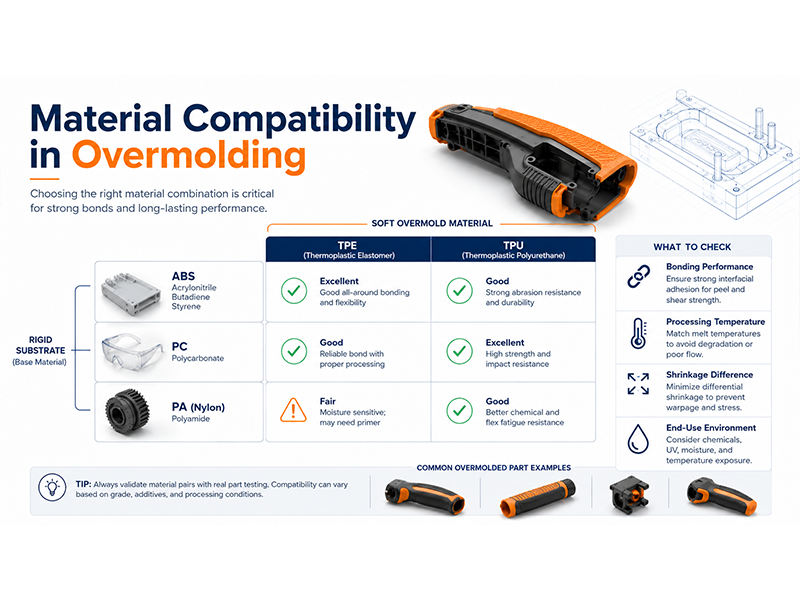
Material compatibility is the foundation of a reliable overmolded part. Two materials may look suitable individually but still fail to bond during overmolding.
Material | Type | Key Properties | Common Applications |
TPE (Thermoplastic Elastomer) | Soft overmold material | Soft touch, flexible, slip-resistant, easy processing, good comfort | Tool handles, consumer electronics, automotive interiors, medical grips |
TPU (Thermoplastic Polyurethane) | Soft overmold material | High abrasion resistance, excellent elasticity, impact resistance, chemical resistance | Protective covers, industrial components, automotive parts |
ABS (Acrylonitrile Butadiene Styrene) | Rigid substrate material | Good impact strength, dimensional stability, excellent surface finish | Electronic housings, consumer products, tool components |
PC (Polycarbonate) | Rigid substrate material | High impact resistance, heat resistance, good mechanical strength | Automotive parts, industrial housings, protective covers |
PA (Nylon) | Rigid substrate material | High strength, wear resistance, durability, excellent mechanical performance | Automotive components, gears, industrial parts |
A successful overmolding project requires the right combination of material selection, part design, and mold manufacturing expertise. With experience in overmolding mold design and injection molding, Alpine Mold helps customers develop reliable overmolded parts through professional DFM analysis, precision mold manufacturing, mold trials, and production support.
If you are looking for a reliable overmolding manufacturer, please send your 3D drawings (STEP, IGS, or X-T files) and project requirements. Our engineering team will review your design and provide a suitable solution and quotation.
Overmolding usually involves producing the substrate first and then placing it into another mold for the second injection process. Two-shot molding completes both material injections within one molding cycle using a specialized machine and rotating or moving mold structure. Two-shot molding is more automated, while traditional overmolding can be more flexible for lower production volumes.
Yes. An existing molded part can be used as the substrate, provided its dimensions, surface condition, heat resistance, and positioning accuracy are suitable for the second molding process. The part must remain stable inside the mold and withstand the temperature and pressure of the overmold material.
The project schedule depends on part complexity, mold structure, testing requirements, and whether the substrate requires a separate mold. Additional time may also be needed for sample testing, design adjustments, and bonding validation before mass production begins.
Yes. Metal inserts, terminals, threaded components, cables, and electronic components can be placed into the mold before plastic or elastomer is injected around them. Accurate insert positioning and secure mold fixing are necessary to prevent movement, flash, or component damage.
Recycled materials may be suitable for some non-critical applications, but their consistency, contamination level, bonding performance, and processing stability must be carefully evaluated. For products with strict appearance, safety, sealing, or durability requirements, controlled virgin materials are usually preferred.


