WhatsApp: +86 18126157548 Email: kerry@alpinemold.com
Views: 0 Author: Site Editor Publish Time: 2025-10-31 Origin: Site


| Table of Contents |
| 1.Introduction |
| 2.The Real "Mold" Problem: Stuck Parts and Surface Defects |
| 3.Your Design Toolkit for Easy Ejection and Faster Time-to-Market |
| 4.The Ultimate Shortcut: Partner with Your Molder Early |
| 5.Conclusion |
If you're searching for "how to get rid of mold on plastic," you've already identified the symptom—but the real problem lies deeper. For engineers and product designers, this isn't an issue of cleaning; it's a fundamental challenge of design for manufacturability (DFM). When your parts stick, drag, or require excessive force to eject, you're facing costly delays, surface d
efects like witness marks and scuffing, and compromised part integrity. These aren't cleaning problems; they are design problems.
The most efficient way to get rid of "mold" on plastic — to ensure clean, effortless part release every time—is to prevent it at the design stage. This guide cuts directly to the core DFM principles that we apply daily to eliminate ejection issues, accelerate development cycles, and slash unexpected costs. Stop treating the symptoms and start designing for seamless production.
If you're searching for how to get rid of "mold" on plastic in a manufacturing context, you're likely dealing with the symptoms of a part that won't release properly. This fundamental issue in plastic part design leads to costly defects and production delays. Understanding why parts get stuck is the first step toward implementing effective injection molding design rules.

Without sufficient draft, the entire part surface grinds against mold walls during ejection. This creates drag marks, scuffing, and requires excessive ejection force that can deform parts or leave visible ejection pin marks on plastic.
Deep ribs, bosses, and cavities can create an airtight seal against mold cores. As the part ejects, it must overcome atmospheric pressure - a force often underestimated in initial design for injection molding calculations.
Undecompensated shrinkage can cause features to mechanically lock onto cores. Combined with high friction surfaces, this creates the perfect storm for having a plastic part stuck in mold situations that damage both parts and tooling.
These issues frequently cascade into other defects. A part struggling to eject transfers stress to thin sections, exacerbating issues like sink marks. Learning how to avoid sink marks often involves addressing ejection problems first, as both relate to proper part solidification and release.
This intersection of physics and geometry is why a comprehensive plastic part design guide must address ejection fundamentals. In the following sections, we'll transform these failure modes into actionable design strategies that ensure reliable part release and superior quality.
Now that we've diagnosed the root causes of ejection problems, let's explore practical design solutions. Mastering these fundamental techniques will transform your approach to plastic part design and provide lasting answers to how to get rid of mold on plastic challenges. These proven injection molding design rules form the foundation of manufacturable components that release smoothly every time.
Think of draft angles as the essential taper that breaks the vacuum seal between your part and the mold. They're the most effective tool in your design for injection molding arsenal for preventing friction-related damage.
Professional Insight:The required draft angle increases significantly with surface texture. For textured surfaces, add 1-2° of additional draft for every 0.025mm (0.001 inches) of texture depth. A polished surface might function with just 0.5° of draft, while a heavy texture could demand 5° or more.
Actionable Guideline:Maintain minimum draft angles of 1-2° on all external walls, and increase to 1.5-3° for internal cores and rib features. Deeper features generally require more generous draft angles to ensure clean release throughout the entire ejection stroke.
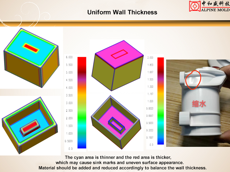
Inconsistent wall thickness creates uneven cooling rates and differential shrinkage - the primary culprits behind warpage and parts that bind against mold cores. This fundamental principle of injection molding design rules directly impacts your success in preventing plastic part stuck in mold scenarios.
Professional Insight:Most engineering thermoplastics perform optimally within 1.5-3.0mm wall thickness ranges. When thickness variations are unavoidable, implement gradual transitions with a maximum 3:1 ratio to minimize stress concentration and differential shrinkage.
Actionable Guideline:Instead of thickening entire sections, strategically place ribs to maintain stiffness while preserving uniform nominal walls. This approach directly addresses how to avoid sink marks while improving ejection reliability.

Ribs and bosses present particular ejection challenges due to their deep, narrow geometries. Proper design of these features significantly impacts your ability to prevent ejection pin marks on plastic and other release-related defects.
Maintain rib thickness at 50-60% of the adjacent nominal wall to prevent sink marks
Apply draft angles to all rib and boss side walls (typically 0.5-1.5°)
Implement radius values of 25-50% of the nominal wall thickness at rib bases
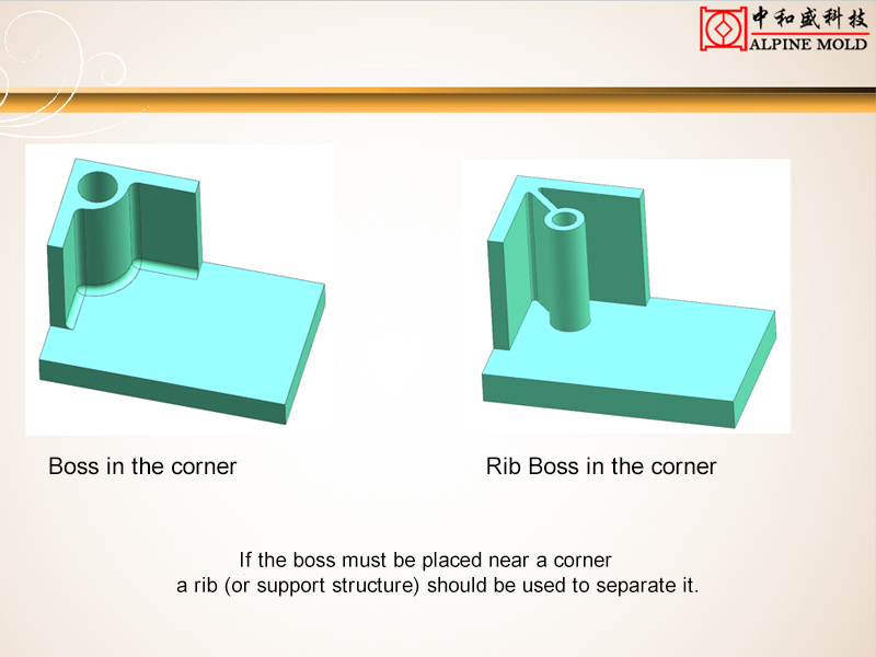
Connect bosses to the main wall structure with supporting ribs rather than thick bases. This maintains strength while promoting even material flow and minimizing mass accumulation that could hinder ejection.

Many designers overlook how their choices affect the mold's ejection system. By considering ejection requirements early in your plastic part design guide process, you ensure the final component can be removed without damage or cosmetic defects.
Professional Insight:Identify natural ejection locations during the design phase. Areas with sufficient stiffness - typically where ribs intersect or near boss features - provide ideal contact points for ejector pins without creating visible ejection pin marks on plastic.
Actionable Guideline:Reinforce potential ejection points with localized ribbing or slight thickening to withstand ejection forces. This proactive approach ensures your components survive the ejection process with flawless surface quality.
These four strategic areas form the core of ejection-optimized design. By implementing these practices, you'll not only solve immediate how to get rid of mold on plastic challenges but also establish a foundation for manufacturing success. In our next section, we'll explore how material selection and advanced DFM analysis can further enhance your results.
While the design principles we've discussed provide a solid foundation, there exists a more efficient path to manufacturing success. Every guideline around draft angles, wall thickness, and ejection planning can be dramatically optimized through one strategic decision: engaging your injection molding partner during the initial design phase.
Think of this approach as preventative medicine for your product development. Instead of treating symptoms like plastic part stuck in mold scenarios or wrestling with how to avoid sink marks through costly iterations, you're implementing immunity at the conceptual stage. This collaborative approach transforms theoretical injection molding design rules into practical, part-specific solutions that work within your exact technical and budgetary constraints.
At our manufacturing facility, we've systematized this collaboration through our comprehensive Design for Manufacturability analysis. When you submit your concepts, our engineering team performs a detailed assessment that examines:
Critical draft angles specific to your geometry and material selection
Wall thickness transitions and potential stress concentrators
Optimal gate locations and ejection strategies tailored to your part
Material flow patterns and potential weld line formations
Identification of features that might cause cosmetic defects
This isn't an automated report but a genuine engineering collaboration. We provide specific, actionable recommendations that enhance your design while maintaining its creative vision and functional requirements. The result is a component that not only meets specifications but does so with significantly reduced tooling modifications, fewer prototyping cycles, and faster time-to-market.
Many product developers express initial hesitation about sharing proprietary designs. We address this through strict confidentiality agreements and a track record of trusted partnerships with brands ranging from startups to established corporations. The minor time investment in sharing your CAD files yields substantial returns in accelerated development schedules and avoided tooling revisions.
The most effective answer to how to get rid of mold on plastic challenges isn't found in any single guideline, but in the partnership that identifies and eliminates potential issues before tool steel is ever cut. This proactive approach transforms your plastic part design guide from a theoretical document into a practical roadmap to manufacturing success.
Ready to experience the DFM difference? Submit your 3D files today for a complimentary manufacturability assessment and discover how our engineering partnership can streamline your path from concept to production.
Ultimately, the most effective approach to how to get rid of mold on plastic lies not in troubleshooting production issues, but in preempting them through intelligent, forward-thinking design. The journey from a perfect digital model to a flawless physical part is paved with practical injection molding design rules that, when implemented correctly, transform potential manufacturing headaches into seamless production runs.
We've explored how fundamental principles—from strategic draft angles and uniform wall thickness to intelligent rib design and ejection planning—form the core of any successful plastic part design guide. These aren't just theoretical concepts but practical tools that directly address real-world challenges like how to avoid sink marks and prevent ejection pin marks on plastic. When integrated early in your development process, these principles become your first and most important line of defense against the frustrating reality of a plastic part stuck in mold.
True manufacturing excellence emerges at the intersection of creative design and production reality. The comprehensive design for injection molding approach we've outlined does more than just prevent defects—it builds a foundation for faster time-to-market, lower production costs, and superior product quality that sets your work apart in competitive markets.
The difference between a good design and a great, manufacturable design often comes down to perspective—seeing your creation through the lens of those who will bring it to life. This is where partnership creates tangible value, transforming individual expertise into collective achievement.
Ready to transform your design approach? Upload your 3D files today for a complimentary DFM analysis and join the growing number of engineers who have discovered a smoother, faster path from prototype to production. Let's turn your design challenges into manufacturing successes, together.
Kinetic sculpture refers to three-dimensional artworks that incorporate movement as a central element of their design and aesthetic appeal. These sculptures can be broadly categorized into two main types: electric-powered sculptures, which utilize motors or mechanical systems to create controlled motion, and wind-driven dynamic sculptures, which harness natural air currents to generate organic, fluid movement.
Yes, absolutely. 3D printing is an excellent technology for creating kinetic sculptures. It allows for the precise fabrication of interlocking parts, gears, and lightweight components directly from a digital model. This enables designers to prototype and produce complex, moving mechanisms that would be difficult or expensive to create using traditional methods.
The printing time for a sculpture can vary significantly, ranging from a few hours for a small, simple piece to several days or even weeks for a large, highly complex model. The primary factors influencing print time include:
Physical Size & Volume: Larger sculptures require more material and longer print paths.
Model Complexity & Detail: Intricate designs with fine details, overhangs, and support structures take longer to print.
Printing Technology & Layer Resolution: Technologies like SLA (Stereolithography) might be slower than FDM (Fused Deposition Modeling) for some models, but higher resolution (thinner layers) always increases print time.
Post-Processing Requirements: The time for support removal, sanding, painting, and assembly is a critical part of the overall timeline.
The cost of a 3D printed sculpture is not a fixed price but is determined by a combination of project-specific factors. Key elements that influence the final cost are:
Sculpture Size & Volume: Directly correlates with the amount of material used.
Print Resolution (DPI): Higher resolution printing often costs more due to longer machine time and finer material usage.
Material Selection: Standard plastics (like PLA, ABS), advanced composites (with carbon fiber or glass fiber), or professional resins all have different price points.
Design Complexity: Complex geometries may require specialized printing techniques, more support material, and longer print times.
Post-Processing & Finishing: Services like sanding, priming, professional painting, clear coating, or assembly add to the overall cost.
Quantity: Unit cost typically decreases for multiple copies due to batch processing efficiencies.
We typically require 3D model files in STL or OBJ format. These are the standard file types that slicing software uses to prepare the model for printing. Ensure your model is "watertight" (a manifold mesh without holes or errors) to ensure a successful print.
The best material depends on the sculpture's requirements. For durable, functional parts and gears, engineering plastics like Nylon (PA) or PETG offer excellent strength and fatigue resistance. For highly detailed, smooth-finish artistic pieces, SLA Resins are ideal. For large, lightweight structures, PLA is a common and cost-effective choice, though it can be more brittle.
Designing for movement requires careful planning. Key considerations include:
Clearances & Tolerances: Incorporating small gaps (typically 0.2mm to 0.5mm) between moving parts to prevent binding.
Strength at Pivot Points: Reinforcing areas where axles, gears, or hinges will be placed.
Minimizing Friction: Using smooth bearings, designing low-friction contact surfaces, and potentially incorporating printed bushings.
Yes, we offer end-to-end services. Our team can assist you from the initial design concept, optimizing your 3D model for printability and movement, to the final printing, post-processing, and assembly of your kinetic sculpture. We provide Design for Manufacturability (DFM) feedback to ensure your artwork is not only beautiful but also functional and reliable.