WhatsApp: +86 18126157548 Email: kerry@alpinemold.com

Views: 0 Author: Site Editor Publish Time: 2026-07-23 Origin: Site


In modern manufacturing, accurate measurement is essential for ensuring that every part meets its design requirements. A CMM machine provides precise CMM measurement by collecting three-dimensional coordinate data from a component. Through reliable CMM inspection, you can verify dimensions, geometric tolerances, and complex features before parts move into assembly or mass production.
Table of Contents
| 1. What Is a CMM Machine? |
| 2. How Does a CMM Machine Work? |
| 3. Four Main Types of Coordinate Measuring Machines |
4. Advantages of CMM Inspection Compared with Other Measurement Methods |
| 5. Conclusion |
| 6. FAQ |
A CMM machine, or Coordinate Measuring Machine, is precision measurement equipment used to inspect the dimensions, shapes, and geometric features of manufactured parts. It measures points on a component along the X, Y, and Z axes and converts them into accurate three-dimensional coordinate data. With CMM measurement, manufacturers can compare a physical part with its CAD model or engineering drawing to identify dimensional deviations. CMM inspection is widely used for mold components, injection molded parts, automotive parts, medical devices, and other products that require strict dimensional accuracy.
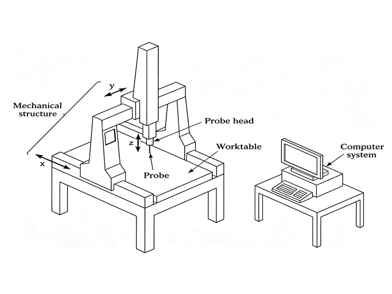
A CMM machine works by collecting precise coordinate data from a part along the X, Y, and Z axes. At Alpine Mold, we use CMM measurement to verify whether mold components and injection molded parts match the approved CAD model, engineering drawing, and tolerance requirements.
Before the CMM inspection begins, we first clean the part and place it securely on the granite measuring table. The component must remain stable throughout the inspection because even small movements can affect the measurement results.
We then select a suitable probe and stylus according to the part size, feature depth, hole diameter, and measurement position. After calibrating the probe, we establish a reference coordinate system based on the datum surfaces, holes, edges, or other features specified in the engineering drawing.
This setup allows us to measure the part from the same reference points used in the product design, helping ensure that the inspection results are accurate, consistent, and repeatable.
Once the setup is complete, the CMM machine moves the probe along the X, Y, and Z axes to collect coordinate points from the part surface. Depending on the feature being inspected, the probe can measure individual points or continuously scan curves, profiles, and complex surfaces.
During CMM measurement, we can inspect features such as:
Overall length, width, and height
Hole diameters and hole positions
Distances between different features
Angles and wall thicknesses
Flatness and straightness
Roundness and cylindricity
Parallelism and perpendicularity
Profile and position tolerances
For mold components, we can measure mold cores, cavities, inserts, sliders, lifters, and other precision parts. For injection molded products, we focus on critical dimensions, assembly positions, sealing areas, hole locations, and features that may be affected by shrinkage or warpage.
After collecting the coordinate data, the CMM software converts the measured points into dimensions and geometric features. We then compare the actual results with the approved 3D model, 2D drawing, and specified tolerances.
The software helps us identify whether each measured feature is within the acceptable range. It can also show the amount and direction of any deviation, allowing our engineering and quality teams to quickly determine whether adjustment is required.
A typical CMM inspection report may include:
Nominal dimensions
Actual measured values
Upper and lower tolerance limits
Dimensional deviations
GD&T inspection results
Pass-or-fail status
If a mold component is outside tolerance, we can correct it before mold assembly or trial. If an injection molded part does not meet the drawing requirements, we can review the mold condition, molding parameters, material shrinkage, cooling balance, or part deformation.
Through this CMM inspection process, we can detect dimensional problems earlier, reduce repeated mold modifications, and provide customers with more reliable quality control before mass production.
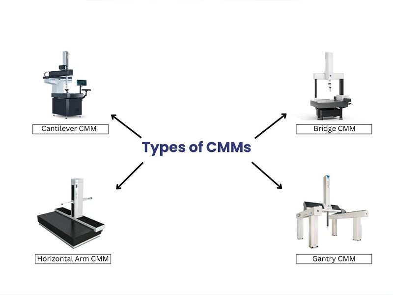
Different CMM equipment is designed for different part sizes, inspection environments, and accuracy requirements. The four main types of coordinate measuring machines are bridge CMMs, cantilever CMMs, gantry CMMs, and horizontal arm CMMs.
A bridge CMM is the most widely used type of CMM machine in precision manufacturing. It has a bridge-shaped structure that moves along the granite measuring table, while the probe travels along the X, Y, and Z axes.
Its rigid and stable structure provides high measurement accuracy and repeatability. Bridge CMMs are commonly used to inspect mold cores, cavities, inserts, machined components, injection molded parts, automotive components, and other medium-sized products with strict dimensional tolerances.
A cantilever CMM has a measuring arm supported on only one side, leaving the other sides of the measuring table open. This design makes it easier to load, unload, and position parts during inspection.
Cantilever CMM machines are commonly used for measuring small precision components, gauges, electronic parts, and lightweight machined parts. They provide convenient access and efficient measurement, although their measuring range is generally smaller than that of bridge or gantry CMM equipment.
A gantry CMM is designed for inspecting large and heavy components. Its bridge structure is supported above the measuring area, allowing oversized parts to be positioned directly within the inspection space.
This type of CMM equipment is commonly used for large molds, automotive components, aerospace structures, heavy machinery parts, and other large products. Gantry CMM machines provide a wide measuring range while maintaining reliable dimensional accuracy.
A horizontal arm CMM uses a probe mounted on a horizontal measuring arm that moves across the side of a component. Its open structure provides easy access to large, thin, or irregularly shaped parts.
Horizontal arm CMM machines are widely used to inspect automotive body panels, doors, dashboards, sheet-metal components, and large plastic parts. They are especially suitable when accessibility and measuring range are more important than the extremely high precision provided by bridge CMM equipment.
Each type of CMM machine has different advantages. The appropriate CMM equipment should be selected according to the part size, geometry, required accuracy, inspection speed, and production environment.
Manual inspection, vision measuring machines, and CMM inspection are suitable for different measurement requirements. The main differences are shown below:
Comparison | Manual Inspection | Vision Measuring Machine | CMM Inspection |
Measurement Method | Calipers, micrometers, and gauges | Camera-based non-contact measurement | Probe-based 3D coordinate measurement |
Suitable Features | Simple dimensions | Visible 2D features | Complex 3D dimensions and geometries |
Accuracy and Repeatability | Depends on operator experience | Good for clear edges and small parts | High accuracy and repeatability |
GD&T Inspection | Limited | Limited for complex 3D tolerances | Suitable for flatness, position, perpendicularity, and other GD&T requirements |
Inspection Report | Usually recorded manually | Digital measurement results | Detailed and traceable digital reports |
Best Application | Quick production checks | Small, thin, or easily deformed parts | Mold components and precision injection molded parts |
Manual inspection is fast and practical for simple dimensions, while vision measuring machines are suitable for non-contact inspection of visible two-dimensional features. For complex parts, strict tolerances, and comprehensive dimensional reports, CMM inspection provides a more accurate and reliable solution.
A CMM machine is an important piece of precision measurement equipment used to verify dimensions, geometric tolerances, and complex three-dimensional features. Compared with manual inspection and vision measuring machines, CMM inspection provides higher repeatability, more complete measurement data, and clearer digital reports for parts with strict accuracy requirements.
At Alpine Mold, we use CMM measurement throughout mold manufacturing, mold trials, and injection molding quality control. By checking critical mold components and molded parts against approved drawings and 3D models, we can identify dimensional deviations earlier, reduce repeated modifications, and help ensure that your parts meet the required specifications before mass production.
A CNC machine manufactures parts by cutting, milling, drilling, or removing material according to a programmed toolpath. A CMM machine does not manufacture the part; it measures the finished component and checks whether its dimensions and geometric tolerances match the drawing or CAD model. Simply put, CNC machines make parts, while CMM machines inspect them.
Most CMM probe balls are made from synthetic ruby rather than simply being painted red. Ruby is extremely hard, smooth, wear-resistant, and suitable for most contact measurement applications. Its red color comes from small amounts of chromium within the ruby material.
PC-DMIS is generally considered one of the most widely used CMM software systems. Hexagon reports that it is installed in more than 70,000 systems worldwide. Other commonly used options include ZEISS CALYPSO and Mitutoyo MCOSMOS. The best choice usually depends on the CMM brand, inspection requirements, and existing quality-control system.
The main disadvantages of a traditional CMM machine include high equipment costs, large installation space, professional programming requirements, and regular probe calibration. Measurement accuracy may also be affected by temperature changes, vibration, humidity, and an unsuitable inspection environment. In addition, contact measurement can be slower when many points or complex features must be inspected.


