WhatsApp: +86 18126157548 Email: kerry@alpinemold.com
Views: 0 Author: Site Editor Publish Time: 2025-09-10 Origin: Site


Table of Contents
| 1.Introduction |
2.Basic Components of an Injection Molding Runner System |
3.Sprue Design Principles |
4.Runner Design Considerations |
5.Gate Design and Selection |
6.Gate Layout and Flow Optimization |
7.Conclusion |
In the plastic injection molding process, the runner system acts as the essential channel that connects the injection unit to the mold cavities. The geometry, dimensions, and balance of the Injection molding runner system directly influence pressure transmission, heat retention, and cavity filling efficiency. A well-designed runner not only minimizes energy consumption and material waste but also ensures consistent part quality and appearance.
Today, manufacturers and mold engineers place great emphasis on Injection Molding Runner System Standards, as optimizing the runner design plays a critical role in balancing flow resistance, reducing heat loss, and supporting precise mold gate design. From a business perspective, this directly impacts both Injection Mold Cost or Part Quality, since the efficiency of the flow path determines material utilization, cycle time, and the likelihood of molding defects.
Another important decision in runner system design is choosing between Hot Runner or Cold Runner systems. Each has advantages depending on material type, part geometry, and production volume. Understanding these options is crucial to achieving an optimal balance between tooling investment and production efficiency.
This article will provide a comprehensive overview of runner system design in injection molds, covering sprue, runner, gate, and cold slug well design. We will also analyze how proper layout and sizing help reduce flow imbalance and ensure uniform cavity filling. By following proven mold runner standards, engineers can greatly enhance the reliability, efficiency, and overall quality of the plastic injection molding process.
A complete Injection molding runner system consists of four main elements: the sprue, runner, gate, and cold slug well. Each of these plays a unique role in ensuring smooth material flow and consistent part quality during the plastic injection molding process. Proper design of these components is essential not only for process stability but also for controlling Injection Mold Cost or Part Quality.
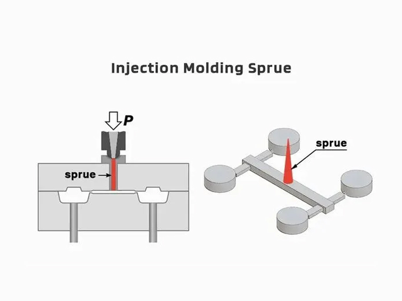
The sprue is the primary channel that connects the injection molding machine nozzle to the runner system. Its design must minimize pressure drop and allow molten plastic to enter the system efficiently. A poorly designed sprue can lead to excessive shear stress and uneven flow distribution, which may negatively affect part strength and surface finish.
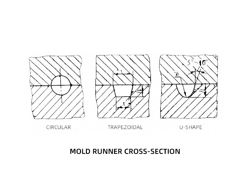
The runner distributes molten plastic evenly to all mold cavities. In multi-cavity molds, balanced runner layouts are critical to avoid short shots or variations in part dimensions. Engineers must carefully select runner cross-sections—such as round, trapezoidal, or U-shaped—based on flow resistance, thermal efficiency, and manufacturability. This aspect of runner system design directly influences productivity and defect rates.
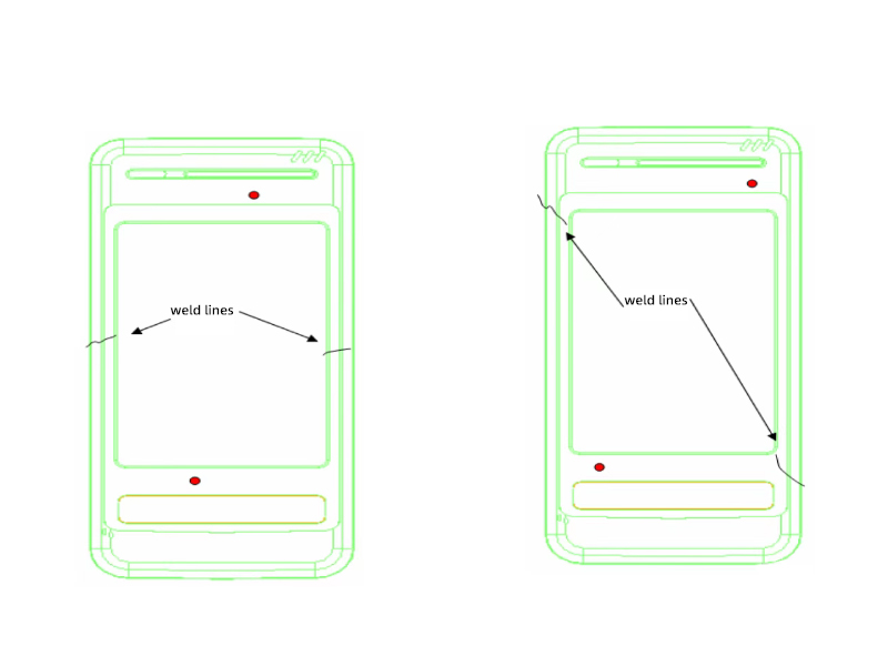
The gate is the smallest section of the mold gate design, acting as the transition point between the runner and the cavity. Gate size, location, and type (e.g., edge gate, pin gate, submarine gate) determine how molten plastic enters the cavity, affecting weld line formation, shrinkage, and surface appearance. Incorrect gate design can lead to warpage, burn marks, or flow imbalance, increasing rework and production costs.
Positioned at the end of the sprue or runner, the cold slug well captures cooled material that forms at the flow front during injection. Without this feature, cold material could enter the cavity and cause visual defects or weak points in the molded part.
These four elements work together as a system. When optimized according to Injection Molding Runner System Standards, they ensure efficient flow, reduced cycle times, and predictable part quality. Whether the tool uses a Hot Runner or Cold Runner system, careful consideration of these components helps balance tooling cost with long-term production efficiency.
The sprue is the entry point of the Injection molding runner system, linking the machine nozzle to the mold’s internal channels. While it may appear simple, the sprue’s geometry and alignment have a direct effect on the stability of the plastic injection molding process. Following proven Injection Molding Runner System Standards in sprue design is critical to ensuring smooth flow and minimizing waste.
A sprue should be tapered rather than cylindrical, typically with a 2–5° angle, to allow easy ejection of the solidified plastic after molding. The diameter must be sufficient to avoid excessive pressure loss, but not so large that it increases material waste. Correct sizing helps achieve a balance between material efficiency and molding consistency.
The sprue should be as short as possible to reduce pressure drop and heat loss. Longer sprues increase cycle time, cooling requirements, and scrap. By minimizing sprue length, manufacturers can lower overall Injection Mold Cost or Part Quality risks while improving efficiency.
Proper alignment between the machine nozzle and the sprue is essential to prevent leakage, flashing, or nozzle wear. Misalignment can lead to flow disturbances that affect the runner balance and final part dimensions.
At the base of the sprue, a cold slug well should be integrated to capture the solidified front material. This prevents unmelted plastic from entering the cavity, which could cause surface defects or reduce mechanical strength of the molded parts.
By applying these principles, engineers ensure that the sprue provides an efficient and stable starting point for the entire Injection molding runner system. Even in Hot Runner or Cold Runner molds, where sprue design may differ, the goal remains the same: to optimize flow, reduce energy consumption, and improve consistency in part quality.
The runner is the transitional channel between the sprue and the mold cavities in an Injection molding runner system. Its design is crucial for distributing molten plastic evenly to all cavities, ensuring uniform part quality and reducing production defects. Optimizing runner system design directly impacts both Injection Mold Cost or Part Quality and cycle efficiency.
4.1 Cross-Section Shape
Runner cross-sections can be round, U-shaped, or trapezoidal.
Round runners offer minimal surface area, reducing heat loss and flow resistance, which improves flow efficiency. However, they require precise alignment of the mold halves, making manufacturing more complex.
U-shaped runners are easier to machine and demold, offering a good balance between flow efficiency and manufacturability.
Trapezoidal runners are used when specific flow control or part ejection considerations are needed.
Selecting the right shape follows Injection Molding Runner System Standards, balancing flow resistance, thermal management, and ease of fabrication.
Runner diameter should be proportional to its length and the material’s flow characteristics. For low-viscosity plastics like PP or PE, smaller runners (e.g., 2.5–4.0 mm diameter) are sufficient, while high-viscosity plastics like PC or PMMA require larger runners to prevent short shots.
In multi-cavity molds, maintaining a balanced flow to each cavity is essential. Engineers often adjust runner lengths, diameters, or equivalent hydraulic radii to ensure synchronous filling. Using the pressure drop formula (ΔP = λ·(LorD)·(ρv⊃2;or2)), runner system design can achieve uniform pressure distribution across all cavities, which improves part quality and reduces scrap.
In the Injection molding runner system, one of the key objectives is to minimize pressure drop along the flow path while avoiding excessive material usage. The runner should be as short and thin as practical, ensuring that molten plastic reaches all cavities before any section begins to solidify prematurely. Premature freezing in the runner can cause incomplete filling, short shots, or uneven part density, which directly affects part quality and increases Injection Mold Cost or Part Quality due to scrap and rework.
Optimized runner system design reduces flow resistance, which lowers the required injection pressure and minimizes shear heating. This not only improves energy efficiency during the plastic injection molding process but also protects sensitive materials from thermal degradation. For example, temperature-sensitive plastics such as PMMA or PC can be damaged if excessive shear or pressure is applied due to oversized or poorly balanced runners.
The gate is the transition point between the Injection molding runner system and the mold cavity. Proper mold gate design ensures smooth molten plastic entry, controls cavity pressure, and directly influences part appearance, dimensional accuracy, and mechanical performance. Poor gate design can lead to weld lines, warpage, or sink marks, increasing Injection Mold Cost or Part Quality.
Overview:
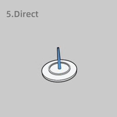
The direct gate, also known as a sprue gate, is the simplest type, allowing molten plastic to flow directly from the sprue into the cavity. It is typically used for single-cavity or large, simple parts.
Advantages:
Short flow path and minimal pressure loss
Simple mold structure and lower tooling cost
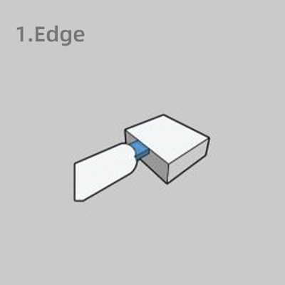
Overview:
An edge gate is positioned on the parting line, allowing melt to enter from the side of the cavity. It is a commonly used gate type in injection molding.
Advantages:
Simple to design and machine
Supports larger gate cross-section
Easy gate removal by trimming
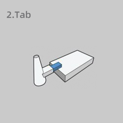
Overview:
A tab gate is an enhanced form of the edge gate, designed to reduce shear stress and jetting by spreading the melt flow. It appears as a wide, flat transition area before the melt enters the cavity.
Advantages:
Minimizes shear-induced defects
Improves surface finish
Shares the benefits of an edge gate
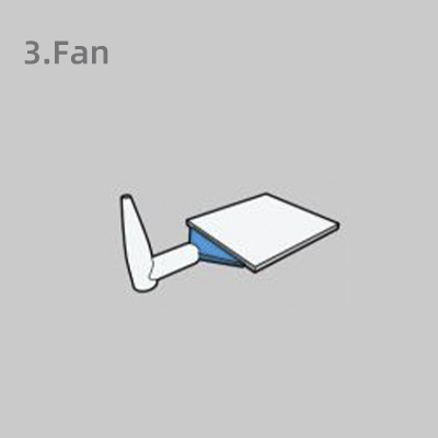
Overview:
The fan gate expands the flow path laterally, distributing melt evenly across a wide area, reducing warpage and stress concentration.
Advantages:
Ensures uniform melt flow
Minimizes air entrapment and cosmetic defects
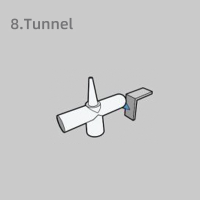
Overview:
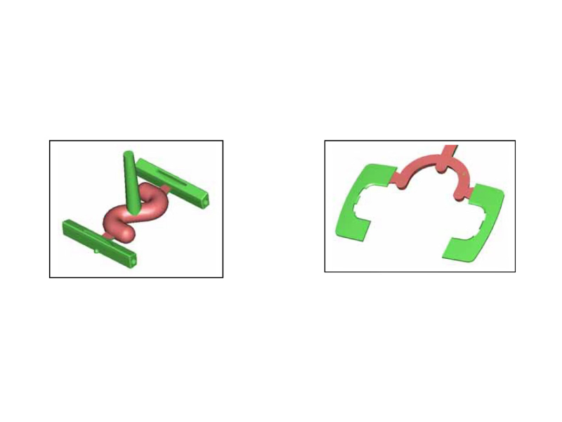
Also known as a sub-gate, the tunnel gate enters the cavity beneath the parting line, creating a hidden gate location in injection molding.
Advantages:
Gate separates automatically during ejection
Minimal gate mark; good for cosmetic parts
Suitable for both two- and three-plate molds
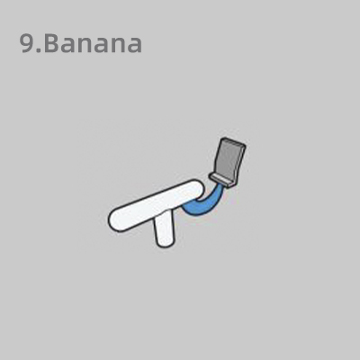
Overview:
A curved variation of the tunnel gate, the banana gate enables the melt to enter from behind or undercut areas of the mold cavity.
Advantages:
Invisible gate location
Supports automated ejection
Preserves front-facing aesthetics
Overview:
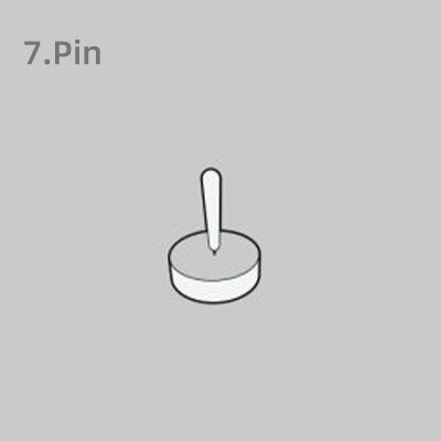
A pin point gate has a very small diameter, typically placed at the center or hidden side of the molded part. It is common in multi-cavity and precision plastic parts.
Advantages:
Very small gate mark
Automatic gate separation
Lower stress and good dimensional control
The gate’s cross-sectional area is typically 5–20% of the runner area to provide proper flow resistance.
Gate location should follow the shortest flow path principle while avoiding thin sections or areas prone to weld lines.
For long or flat parts, placing gates at one end ensures uniform shrinkage along the flow direction.
High-viscosity materials like PC or PPO require larger gates to reduce filling pressure, while low-viscosity plastics like PP or PE benefit from smaller gates to increase shear and flow uniformity. Transparent or high-appearance parts often use submarine or pin gates to hide gate marks.
Type | PVC | PE | PP | PC | PA | POM | ABS | PMMA |
Direct | √ | √ | √ | √ | √ | √ | √ | √ |
Edge | √ | √ | √ | √ | √ | √ | √ | √ |
Tab | √ | √ | √ | |||||
Fan | √ | √ | √ | |||||
Tunnel | √ | √ | √ | |||||
Banana | √ | √ | √ | √ | ||||
Pin | √ | √ | √ | √ | √ | √ |
Optimizing mold gate design within the Injection molding runner system reduces cycle time, material waste, and post-processing, improving both Injection Mold Cost or Part Quality. Correct gate design also ensures consistent cavity filling, which is critical for multi-cavity molds to achieve synchronized flow and uniform plastic injection molding process performance.
Proper mold gate design and strategic gate placement are critical to achieving uniform filling and high-quality parts in the plastic injection molding process. For multi-cavity molds, an optimized gate layout ensures synchronized cavity filling, reduces internal stresses, and minimizes defects such as warpage, weld lines, or sink marks.
Gates should follow the shortest, most balanced flow paths from the Injection molding runner system to each cavity.
Avoid locating gates near thin sections or weak areas of the part to prevent premature cooling, weld lines, or incomplete filling.
For long or flat parts, positioning gates at one end or multiple balanced points ensures consistent shrinkage and minimizes internal stresses.
In multi-cavity molds, unequal runner lengths or diameters can lead to pressure differences, causing some cavities to fill faster than others.
Engineers use simulation tools (CAE) to adjust runner and gate dimensions, achieving balanced flow and synchronized filling.
Optimized flow reduces cycle time, minimizes scrap, and improves repeatability, positively impacting Injection Mold Cost or Part Quality.
High-viscosity materials (PC, PPO) may require larger gates to reduce filling pressure.
Low-viscosity materials (PP, PE) benefit from smaller gates to improve shear and flow uniformity.
For transparent or cosmetic-critical parts, submarine or pin gates are preferred to hide gate marks and maintain surface quality.
Hot runner systems allow precise control of flow to each cavity, reducing material waste and cycle time.
Cold runner systems require careful gate placement to ensure balanced flow, maintain melt temperature, and avoid trapped cold material.
Optimizing gate layout and flow within the Injection molding runner system improves part quality, reduces scrap, and enhances production efficiency. Correct gate placement minimizes defects, ensures consistent cavity filling, and ultimately lowers Injection Mold Cost or Part Quality.
Optimizing your Injection molding runner system and mold gate design is key to achieving superior part quality, efficient cycle times, and controlled Injection Mold Cost or Part Quality in the plastic injection molding process. From careful runner sizing and gate placement to strategic flow balance and cold slug well integration, every design choice impacts the final product’s performance and aesthetics.
Partnering with a mold manufacturer that understands these critical principles can significantly improve production efficiency and reduce scrap. With over two decades of expertise, our factory delivers tailored injection molds and Hot Runner or Cold Runner solutions that meet the highest quality standards.
Contact us today to discuss your project and experience the benefits of working with a trusted partner for precision injection molding and mold solutions.


